Post by biged on Dec 23, 2007 7:53:37 GMT -5
I did this mod because the load on trigger will cause the gun to stop working.
This mod was for the G&G M14 but can be adapted for the AGM series.
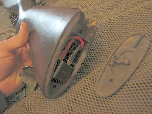
Space is a luxury on the G&G M14, you can fit a 12v battery in the stock without any mods. So a 9.6v and the relay fits easily.
My gun runs a systema M150, 9.6v Intellect, cut down PSG1 6.03mm barrel, Systema Torque up gears, Head spaced piston with 2nd tooth removed, feather trigger mod and an auto relay trigger.
Instructions
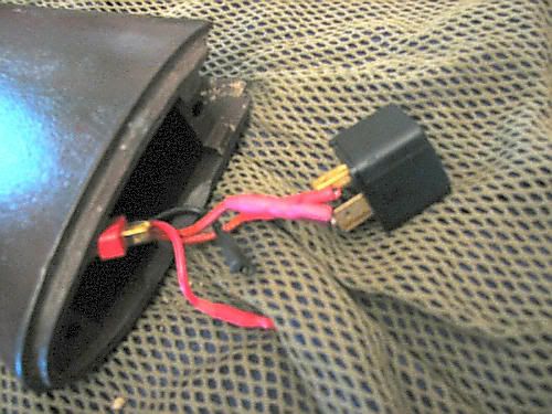
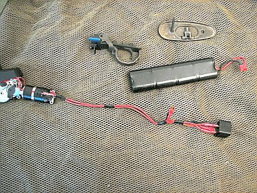
There are 4 wires and an automotive relay that are added to the setup.
It may take up to an hour to complete it.
Tools needed:
Wire strippers
Soldering iron
lighter (heat the shrink wrap)
What you need: (You can get everything at Radio Shack except the deans connectors.)
Automotive relay
Red 16 gauge wire
Red 14 gauge wire
Black 14 gauge wire
(4) 1/4" Female crimp-on connectors, 1 additional connector for Active Braking
Deans connectors
Shrink wrap
Solder
Flux
Soldering Tips:
Always use flux on your electrical connections. Flux allows solder to flow and stick to the surface you are soldering. Get electrical grade solder and flux. Do not use solder that is intended to be used for plumbing.
Keep the tip of your soldering iron tight. There are usually 2 hex head screws that hold the tip of the soldering iron on. Keep them tight and the tip will heat up faster.
Keep the tip of your soldering iron clean. Get the soldering iron good and hot. Get a wet sponge and wipe the tip on it quickly. All the black crud should wipe off. Before putting the soldering iron away - clean the tip.
Wiring reference table:
A - Original red wire leads to the + tamiya connector.
B - Original black wire that leads to the - tamiya connector.
C - New red 14 gauge wire (13 inches long) -- You can use 12 gauge wire.
D - New red 16 gauge wire (13 inches long)
E - New black 16 gauge wire (4 inches long)
F - New red 14 gauge wire (4 inches long) -- You can use 12 gauge wire.
G - New black 16 gauge wire 2 inches long for Active Braking on SPDT relay
Step 1 - Preparation
1. Strip 3/16" of insulation off both ends of the new wires C,D,E and F.
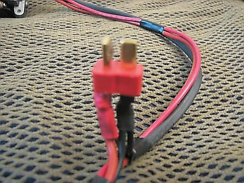
Step 2 - Add the deans connector.
1. Cut the old tamiya connector off very close to the connector end. Strip off 3/16th of insulation from both black and red wires.
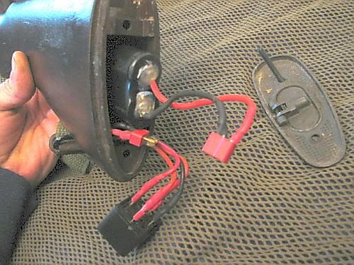
2. Solder wires A (original red) and F to the positive connector on the deans connector. (Shrink Wrap)
3. Solder wires B (original black) and E to the negative connector on the deans connector. (Shrink wrap)
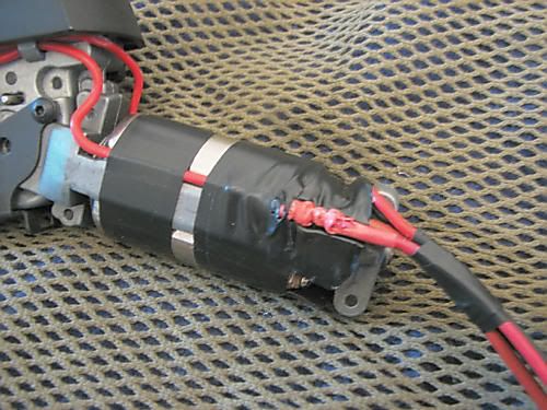
Step 3 - The motor connections.
1. De-solder the red wire on the motor. (Usually on the left side of gun.)
2. Solder togather the red wire you just de-soldered and wire D. (Shrink wrap)
3. Solder on wire C to the motor.
Step 4 - The relay.
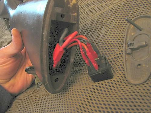
1. Solder on the 1/4 inch connectors to the ends of wires C, D, E, F, (and G). (Shrink wrap)
2. Connect wire D to terminal 85.
3. Connect wire E to terminal 86.
4. Connect wire F to terminal 87.
5. Connect wire C to terminal 30.
6. Solder the end of the Braking wire "G" to the bottom of terminal 86 on the relay. (Solder it to the bottom so you can still get wire D on.)
7. Connect wire G to terminal 87A.
Step 5 - Test it.
1. Test fire it now before you re-assemble it.
If it does not function - check the connections on the relay. Read the packaging.
Step 6 - Re-assembly.
1. Take a marker (Sharpie) and write down numbers on the CONNECTORS and corresponding numbers ON THE RELAY. I numbered mine 1-4. I'm going to locate a white marker someday to make it easier to read.
2. Disconnect the relay (except the brake wire) and feed the wires through the stock.
3. Attach the trigger group.
4. Reconnect the contacts to the relay.
5. Test fire the gun again.
When you pull the trigger instead of the load running through the trigger contacts it runs through the relay which can handle the load and heat 4x times better than the standard trigger contacts.
With Active Braking when the trigger connection is broken, the relay is deactivated, and the flow of electrons is funneled back to the negative side of the battery, immediately stopping the motor.
I added small pieces of electrical tape to keep the wires neat. Then gave a single e-tape wrap to the motor and the wires.
///ed///
This mod was for the G&G M14 but can be adapted for the AGM series.
Space is a luxury on the G&G M14, you can fit a 12v battery in the stock without any mods. So a 9.6v and the relay fits easily.
My gun runs a systema M150, 9.6v Intellect, cut down PSG1 6.03mm barrel, Systema Torque up gears, Head spaced piston with 2nd tooth removed, feather trigger mod and an auto relay trigger.
Instructions
There are 4 wires and an automotive relay that are added to the setup.
It may take up to an hour to complete it.
Tools needed:
Wire strippers
Soldering iron
lighter (heat the shrink wrap)
What you need: (You can get everything at Radio Shack except the deans connectors.)
Automotive relay
Red 16 gauge wire
Red 14 gauge wire
Black 14 gauge wire
(4) 1/4" Female crimp-on connectors, 1 additional connector for Active Braking
Deans connectors
Shrink wrap
Solder
Flux
Soldering Tips:
Always use flux on your electrical connections. Flux allows solder to flow and stick to the surface you are soldering. Get electrical grade solder and flux. Do not use solder that is intended to be used for plumbing.
Keep the tip of your soldering iron tight. There are usually 2 hex head screws that hold the tip of the soldering iron on. Keep them tight and the tip will heat up faster.
Keep the tip of your soldering iron clean. Get the soldering iron good and hot. Get a wet sponge and wipe the tip on it quickly. All the black crud should wipe off. Before putting the soldering iron away - clean the tip.
Wiring reference table:
A - Original red wire leads to the + tamiya connector.
B - Original black wire that leads to the - tamiya connector.
C - New red 14 gauge wire (13 inches long) -- You can use 12 gauge wire.
D - New red 16 gauge wire (13 inches long)
E - New black 16 gauge wire (4 inches long)
F - New red 14 gauge wire (4 inches long) -- You can use 12 gauge wire.
G - New black 16 gauge wire 2 inches long for Active Braking on SPDT relay
Step 1 - Preparation
1. Strip 3/16" of insulation off both ends of the new wires C,D,E and F.
Step 2 - Add the deans connector.
1. Cut the old tamiya connector off very close to the connector end. Strip off 3/16th of insulation from both black and red wires.
2. Solder wires A (original red) and F to the positive connector on the deans connector. (Shrink Wrap)
3. Solder wires B (original black) and E to the negative connector on the deans connector. (Shrink wrap)
Step 3 - The motor connections.
1. De-solder the red wire on the motor. (Usually on the left side of gun.)
2. Solder togather the red wire you just de-soldered and wire D. (Shrink wrap)
3. Solder on wire C to the motor.
Step 4 - The relay.
1. Solder on the 1/4 inch connectors to the ends of wires C, D, E, F, (and G). (Shrink wrap)
2. Connect wire D to terminal 85.
3. Connect wire E to terminal 86.
4. Connect wire F to terminal 87.
5. Connect wire C to terminal 30.
6. Solder the end of the Braking wire "G" to the bottom of terminal 86 on the relay. (Solder it to the bottom so you can still get wire D on.)
7. Connect wire G to terminal 87A.
Step 5 - Test it.
1. Test fire it now before you re-assemble it.
If it does not function - check the connections on the relay. Read the packaging.
Step 6 - Re-assembly.
1. Take a marker (Sharpie) and write down numbers on the CONNECTORS and corresponding numbers ON THE RELAY. I numbered mine 1-4. I'm going to locate a white marker someday to make it easier to read.
2. Disconnect the relay (except the brake wire) and feed the wires through the stock.
3. Attach the trigger group.
4. Reconnect the contacts to the relay.
5. Test fire the gun again.
When you pull the trigger instead of the load running through the trigger contacts it runs through the relay which can handle the load and heat 4x times better than the standard trigger contacts.
With Active Braking when the trigger connection is broken, the relay is deactivated, and the flow of electrons is funneled back to the negative side of the battery, immediately stopping the motor.
I added small pieces of electrical tape to keep the wires neat. Then gave a single e-tape wrap to the motor and the wires.
///ed///